MAINTENANCE AND REPAIR
ON-VEHICLE SERVICE
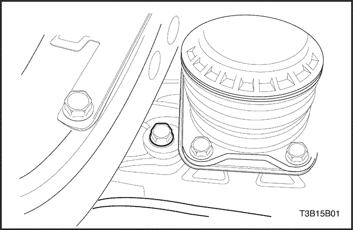


Checking Fluid Level
- With the vehicle on a level surface and the fluid in the transaxle cold, remove the filler plug and check the fluid level. The fluid should come to the bottom edge of the plug hole.
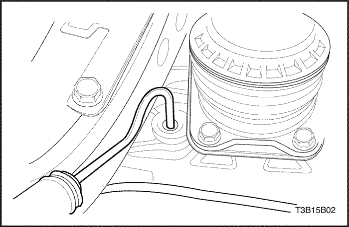
- If the level is low, add SAE75W90 manual transaxle fluid through the filler plug hole until the fluid begins to run out.
- Reinstall the filler plug and tighten it securely.
- If the fluid is contaminated, drain the oil after removing the differential gear cover.
Shift Linkage Adjustment
(Left-Hand Drive shown, Right-Hand Drive Similar)
- Disconnect the negative battery cable.
- Position the gearshift lever into NEUTRAL.
Important : All the gears must be easy to engage when the vehicle is stationary, the engine is running, and the clutch is disengaged.
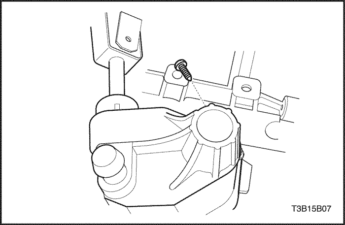
- Loosen the rod clamp bolt.
- Remove the adjustment hole plug from the shift lever cover.
- Turn the gearshift rod and fully insert a 5 mm (0.2 inch) gauge pin into the adjustment hole.
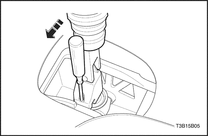
- Remove the boot from the console.
- Pull the boot upward to expose the shift control lever mechanism.
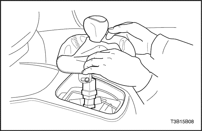
- Position the gearshift lever close to left side of the NEUTRAL position.
- Insert a 5 mm (0.2 inch) gauge pin into the holes to align the gearshift lever with the gearshift lever housing.
- Tighten the rod clamp bolt.
Tighten
Tighten the rod clamp bolt to 14 N•m (124 lb-in).
- Remove the 5 mm (0.2 inch) gauge pin from the adjustment hole.
- Install the adjustment hole plug.
- Remove the 5 mm (0.2 inch) gauge pin from the gearshift lever.
- Install the boot to the console.
- Connect the negative battery cable.
Gearshift Lever
(Left-Hand Drive shown, Right-Hand Drive Similar)
Removal Procedure
- Disconnect the negative battery cable.
- Position the gearshift lever into NEUTRAL.
- Disconnect the boot from the console cover.
- Lift the console cover upward to expose the shift control lever mechanism.
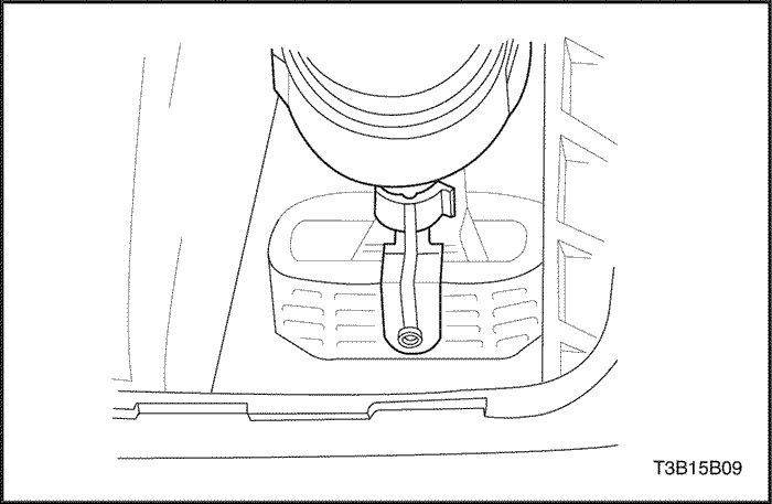
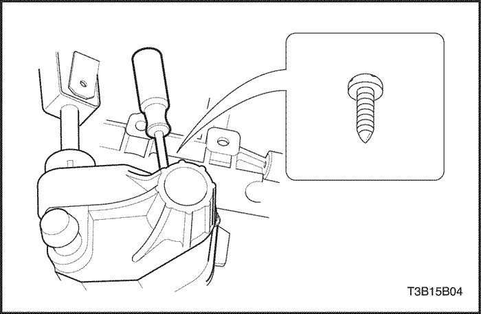
- Rotate the gearshift lever stop clamp and remove it.
- Remove the gearshift lever from the gearshift lever shaft.
Installation Procedure
- Install the gearshift lever into the gearshift lever shaft.
- Install the gearshift lever stop clamp.
- Rotate the gearshift lever stop clamp to secure it.
- Lower the boot and connect it to the console cover.
- Connect the negative battery cable.
Gearshift Lever Housing
(Left-Hand Drive shown, Right-Hand Drive Similar)
Removal Procedure
- Disconnect the negative battery cable.
- Remove the rod clamp. Refer to "Shift Linkage Adjustment" in this section.
- Remove the console.
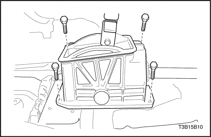
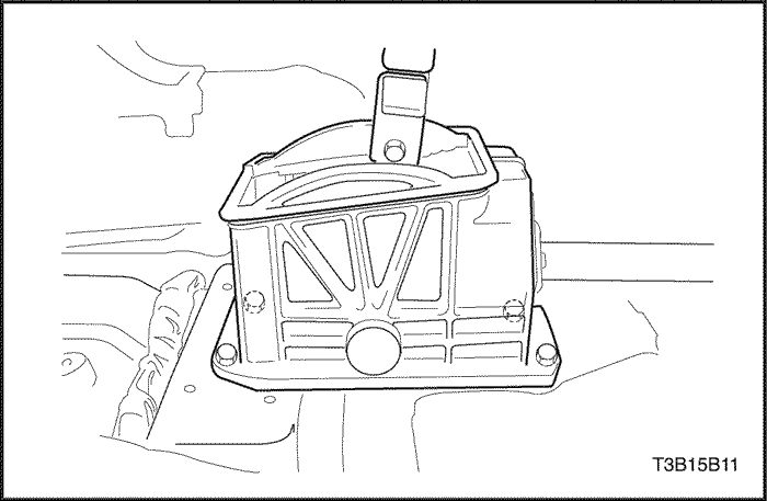
- Remove the gearshift lever housing bolts and the gearshift lever housing.
Installation Procedure
- Install the gearshift lever housing and the gearshift lever housing bolts.
Tighten
Tighten the gearshift housing bolts to 7 N•m ( 62 lb-in).
- Adjust the shift linkage.
- Install the console.
- Connect the negative battery cable.
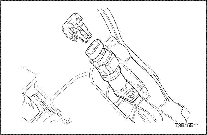
Speedometer Driven Gear
Removal Procedure
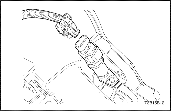
- Disconnect the speedometer speed sensor electrical connector.
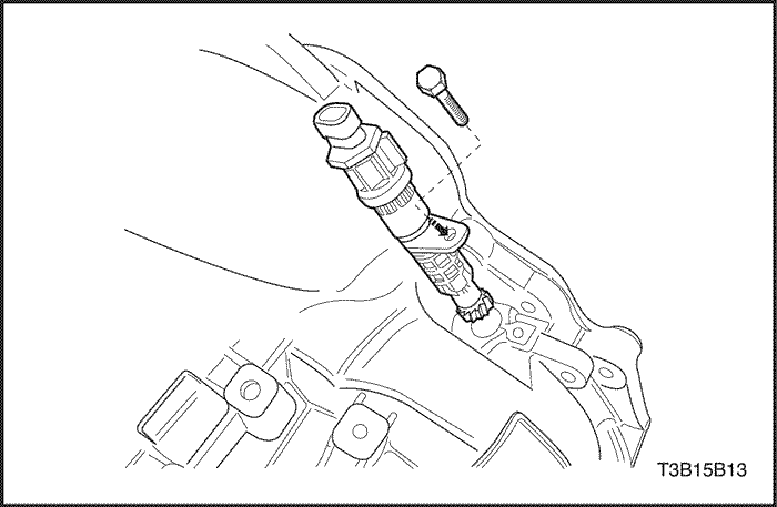
- Remove the speedometer housing retaining bolt.
- Remove the speedometer-driven gear and the speedometer housing.
Installation Procedure
- Coat the O-ring with petroleum jelly.
- Install the speedometer-driven gear and the speedometer housing.
- Install the speedometer housing retaining bolt.
Tighten
Tighten the speedometer housing retaining bolt to 4 N•m (35 lb-in).
- Connect the speedometer speed sensor electrical connector.
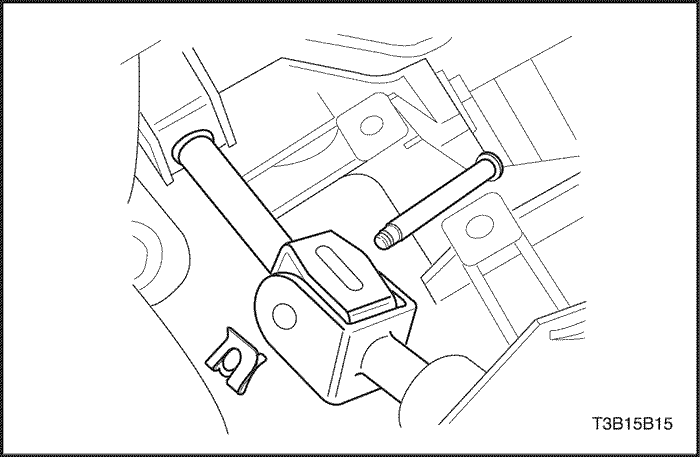
Shift Linkage Assembly
Removal Procedure
- Disconnect the negative battery cable.
- Remove the rod clamp. Refer to "Shift Linkage Adjustment" in this section.
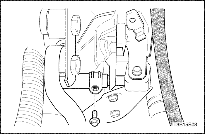
- Remove the clip and the bolt from universal joint.
- Separate the universal joint from the transaxle.
- Remove the fixing shaft pin and separate the linkage connection part from the transaxle rear mounting bracket.
- Remove the shift linkage assembly.
Installation Procedure
- Install the shift linkage assembly.
- Install the fixing shaft pin and connect the linkage connection part to the transaxle rear mounting bracket.
- Install the universal joint to the transaxle.
- Install the clip and the bolt from universal joint.
- Install the rod clamp. Refer to "Shift Linkage Adjustment" in this section.
- Adjust the shift linkage. Refer to "Shift Linkage Adjustment" in this section.
- Connect the negative battery cable.
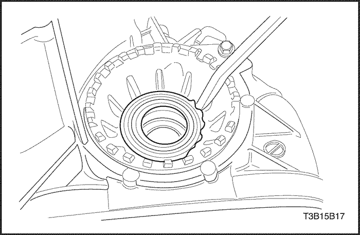
Drive Axle Seal
Tools Required
Removal Procedure
Notice : Do not damage the bearing adjusting ring with the pry bar.
- Remove the drive axle from the transaxle. Refer to Section 3B, Manual Transaxle Drive Axle.
- Remove the drive axle seal by lifting the outer lip of the seal with a pry bar.
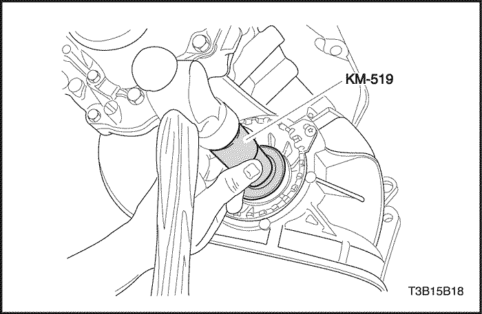
Installation Procedure
- Install the new drive axle seal using the ring installer KM-519 and a hammer.
- Coat the seal lip with the transaxle fluid.
- Install the drive. Refer to Section 3B, Manual Transaxle Drive Axle.
Transaxle Assembly
Tools Required
J-28467-B Engine Support Fixture
Removal Procedure
- Install the engine support fixture J-28467-B.
- Remove the battery and battery tray. Refer to Section 1E, Engine Electrical.
- Remove the shift linkage assembly. Refer to "Shift Linkage Adjustment" in this section.
- Remove the drive axle shaft. Refer to Section 3A, Automatic Transaxle Drive Axle.
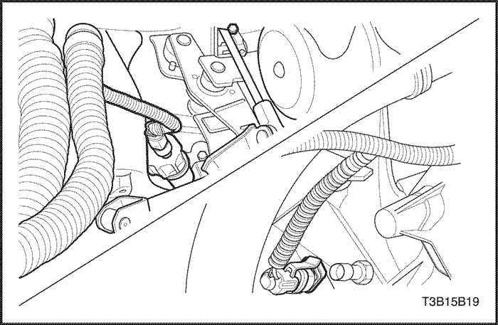
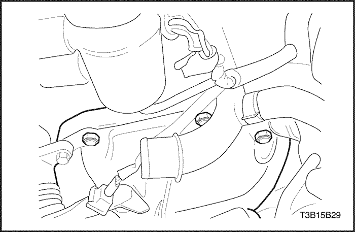
- Disconnect the backup lamp switch electrical connector.
- Disconnect the speedometer speed sensor electrical connector.
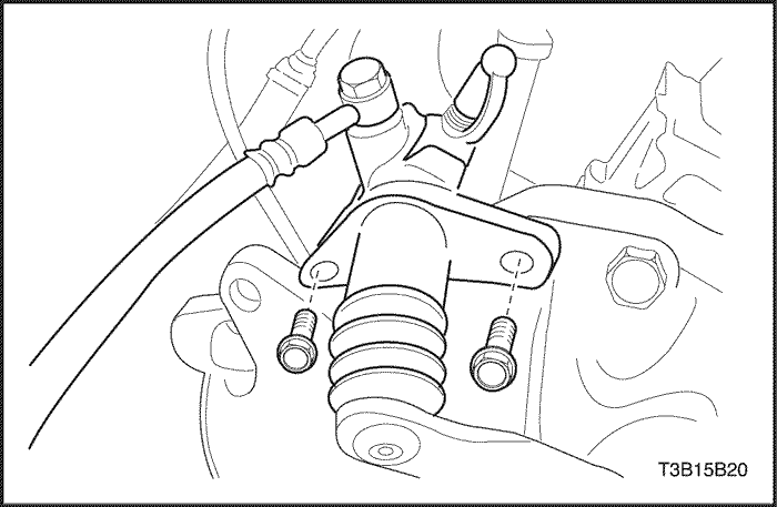
- Remove the clutch release cylinder retaining bolts and the clutch release cylinder.
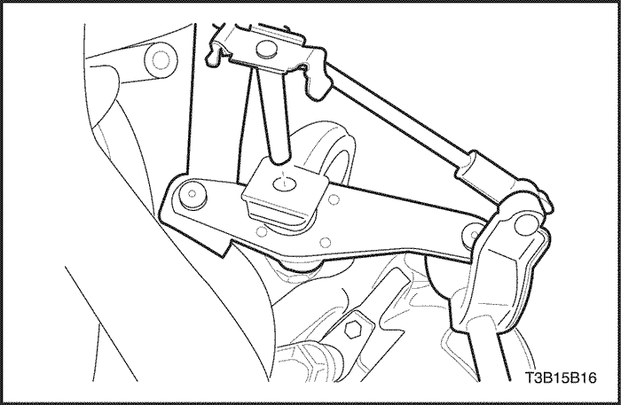
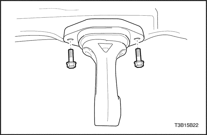
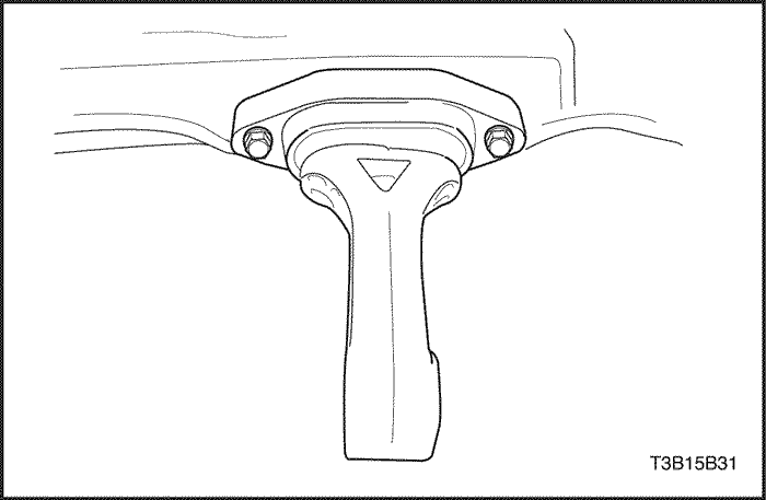
- Remove the damping block connection nut and bolt.
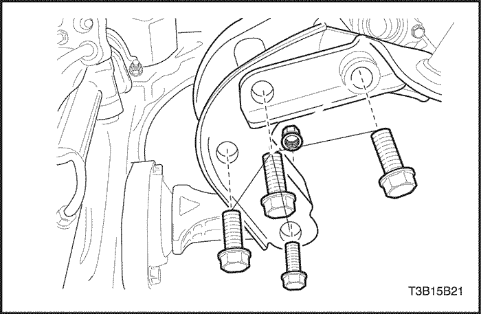
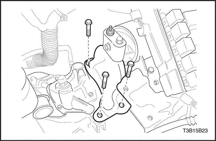
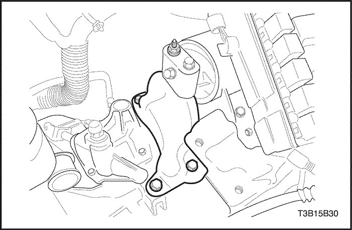
- Remove the three rear mounting bracket bolts.
- Remove the rear mounting bracket from the transaxle.
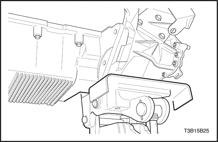
- Remove the two rear damping block retaining bolts.
- Remove the rear damping block from the front cross member.
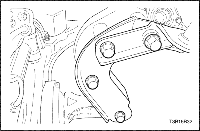
- Remove the two cage retaining bolts.
- Remove the three transaxle upper mounting bracket bolts.
- Remove the upper mounting bracket and cage.
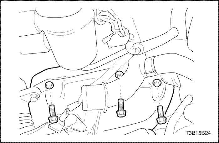
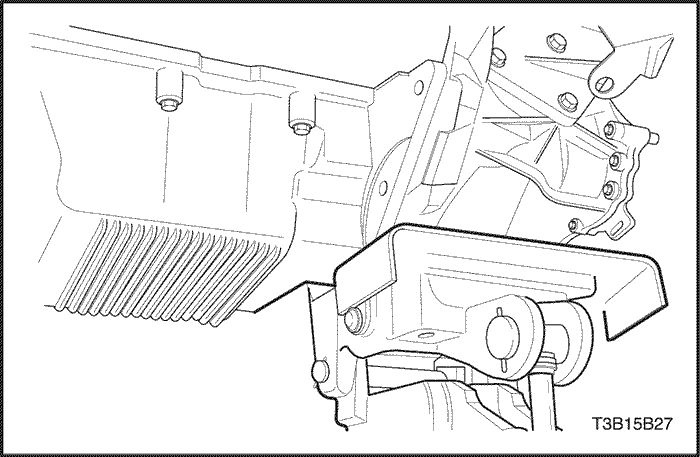
- Remove the three transaxle upper retaining bolts.
- Support the transaxle with a transaxle support jack.
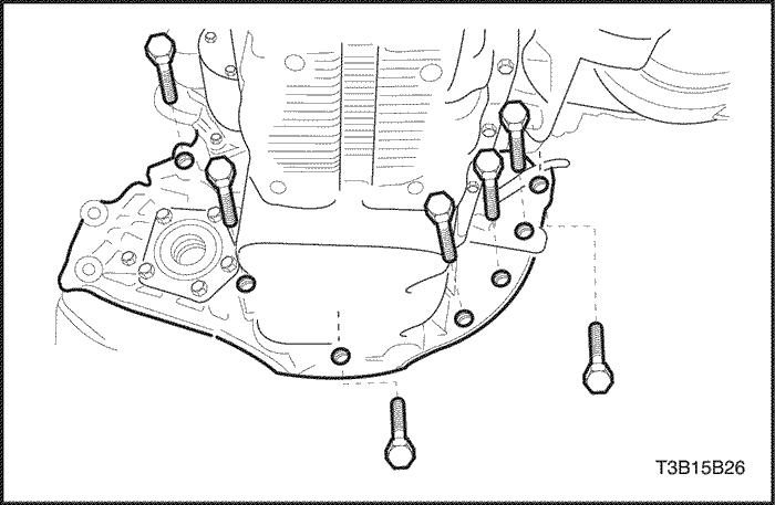
- Remove the seven transaxle lower retaining bolts.
- Remove the transaxle.
Notice : Rest the transaxle only in an upright position.
- Slide the transaxle sideways away from the engine block.
- Lower the transaxle.
Installation Procedure
- Support the transaxle with a transaxle support jack.
- Install the transaxle by inserting the transaxle input shaft into the clutch disc and sliding the transaxle sideways into the engine block.
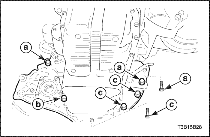
- Install the seven transaxle lower retaining bolts.
Tighten
Tighten the transaxle lower retaining bolts(a) to 73 N•m ( 54 lb-ft ).
Tighten the transaxle lower retaining bolt(b) to 31 N•m ( 23 lb-ft ).
Tighten the transaxle lower retaining bolts(c) to 21 N•m ( 15 lb-ft ).
- Install the three transaxle upper retaining bolts.
Tighten
Tighten the transaxle upper retaining bolts to 73 N•m (54 lb-ft ).
- Install the cage retaining bolt and cage.
- Install the three transaxle upper mounting bracket bolts and bracket.
Tighten
Tighten the transaxle upper mounting bracket bolts to 60 N•m (44 lb-ft ).
- Install the two rear damping block retaining bolts.
Tighten
Tighten the rear damping block retaining bolts to 55 N•m (41 lb-ft ).
- Install the rear damping block from the front cross member.
- Install the three rear mounting bracket bolts and the bracket.
Tighten
Tighten the rear mounting bracket bolts to 80 N•m (59 lb-ft ).
- Install the damping block connection nut and bolt.
Tighten
Tighten the damping block connection nut and bolt to 80 N•m (59 lb-ft ).
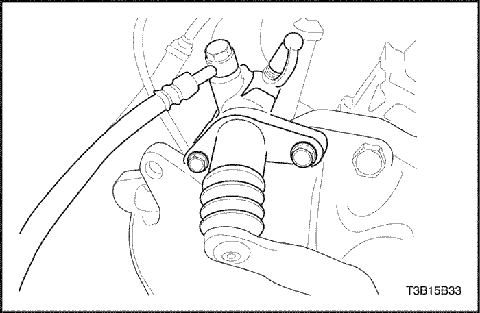
- Install the clutch release cylinder retaining bolts and the clutch release cylinder.
Tighten
Tighten the clutch release cylinder retaining bolts to 20 N•m (15 lb-ft ).
- Connect the speedometer speed sensor electrical connector.
- Connect the backup lamp switch electrical connector.
- Remove the engine support fixture J-28467-B.
- Install the drive axle shaft. Refer to Section 3A, Automatic Transaxle Drive Axle.
- Install the shift linkage assembly. Refer to "Shift Linkage Assembly" in this section.
- Install the battery and battery tray. Refer to Section 1E, Engine Electrical.
- Inspect the fluid level. Refer to "Checking Fluid Level" in this section.
 | |  | |
| © Copyright Chevrolet Europe. All rights reserved |


