DIAGNOSTIC TROUBLE CODE DIAGNOSIS
Diagnostic Trouble Code Chart
DTC | DESCRIPTION | TYPE | Illuminate MIL | Blink Hold Lamp |
P0562 | System Voltage Low | B | Yes | No |
P0563 | System Voltage High | B | Yes | No |
P0601 | Internal Control Module Memory Checksum Error | A | Yes | No |
P0604 | Internal Control Module Random Access Memory (RAM) Error | B | Yes | No |
P0705 | Transmission Range (TR) Switch Circuit Malfunction (No Signal) | B | Yes | No |
P0706 | Transmission Range (TR) Switch Circuit Malfunction (Short) | B | Yes | No |
P0711 | Transmission Fluid Temperature(TFT) Sensor Circuit Performance | A | Yes | No |
P0712 | Transmission Fluid Temperature Sensor Circuit Low Input | A | Yes | No |
P0713 | Transmission Fluid Temperature Sensor Circuit High Input | A | Yes | No |
P0717 | Input Shaft Speed (ISS) Sensor Circuit No Signal | A | Yes | No |
P0722 | Output Shaft Speed (OSS) sensor Circuit No Signal | A | Yes | No |
P0741 | Torque Converter Clutch (TCC) Circuit Performance or Stuck ON | B | Yes | No |
P0742 | Torque Converter Clutch (TCC) Circuit Stuck ON | B | Yes | No |
P0751 | Shift Solenoid 1 (SS1) Performance or Stuck OFF | B | Yes | No |
P0752 | Shift Solenoid 1 (SS1) Performance or Stuck ON | B | Yes | No |
P0756 | Shift Solenoid 2 (SS2) Performance or Stuck OFF | B | Yes | No |
P0757 | Shift Solenoid 2 (SS2) Performance or Stuck ON | B | Yes | No |
P0787 | Timing Solenoid (ST) Electrical (Ground Short) | A | Yes | No |
P0788 | Timing Solenoid (ST) Electrical (Open or Power Short) | A | Yes | No |
P0962 | Pressure Control Solenoid (PCS) Electrical (Low) | A | Yes | No |
P0963 | Pressure Control Solenoid (PCS) Electrical (High) | A | Yes | No |
P0973 | Shift Solenoid 1 (SS1) Electrical (Ground Short) | A | Yes | No |
P0974 | Shift Solenoid 1 (SS1) Electrical (Open or Power Short) | A | Yes | No |
P0976 | Shift Solenoid 2 (SS2) Electrical (Ground Short) | A | Yes | No |
P0977 | Shift Solenoid 2 (SS2) Electrical (Open or Power Short) | A | Yes | No |
P2769 | Torque Converter Clutch (TCC) Electrical (Ground Short) | B | Yes | No |
P2770 | Torque Converter Clutch (TCC) Electrical (Open or Power Short) | B | Yes | No |
U0001 | High Speed CAN Communication Bus | A | Yes | No |
U0100 | Lost Communication with ECM/PCM | A | Yes | No |
U0401 | Invalid Data Received from ECM/PCM | C1 | No | Yes |
* Description of Type
- Type A : TCM will request the illumination of MIL and store DTC when TCM detects a failure on the first ignition cycle.
- Type B : TCM will request the illumination of MIL and store DTC when TCM detects failures on two consecutive ignition cycle.
- Type C1 : TCM will request the illumination of hold lamp and store DTC.


Diagnostic Trouble Code (DTC) P0562
System Voltage Low
Conditions for Running the DTC
- Ignition ON.
- No failure condition of CAN Bus OFF.
- No failure condition of engine revolution.
- Engine revolution is greater than 400 rpm.
- No failure condition of input speed sensor revolution.
- Input speed sensor revolution is greater than 400 rpm.
- Ignition voltage is less than 8 volts for 1 seconds continuously.
Conditions for Setting the DTC
- Above detection continuously occurs 20 times.
Action Taken When the DTC Sets
- TCM will request the illumination of MIL and store DTC when TCM detects failures on two consecutive ignition cycle.
Conditions for Clearing the DTC
- The TCM turns off the MIL when no further failures detected for three consecutive ignition cycles.
- The scan tool can clear the DTC from the TCM history.
- The TCM clears the DTC from the TCM history memory after forty consecutive warm up cycles without fault.
Cause of Failure
- TCM wiring harness and connectors
- Battery
- TCM
DTC P0562 - System Voltage Low
| Step | Action | Value(s) | Yes | No |
| 1 | - Turn the ignition OFF.
- Install the Scan tool.
- Turn the ignition ON, with the engine OFF.
- Run the engine to 600 rpm or greater.
- Record then clear DTC(s).
- Select system voltage on the scan tool.
- Drive the vehicle and observe the scan tool for either of the flowing conditions:
Is the voltage within the values shown? | 9-16v | Go to Step 4 | Go to Step 2 |
| 2 | - Disconnect the battery cable.
- Measure the battery voltage.
Is the voltage within the values shown? | 9-16v | Go to Step 4 | Go to Step 3 |
| 3 | - Replace the battery.
Is the replacement completed? | - | System OK | - |
| 4 | - Turn the headlamp ON.
- Turn the air conditioner ON.
- Run the engine to 600 rpm or greater.
- Observe the scan tool for system voltage.
Is the voltage within the values shown? | 9-16v | Go to Step 6 | Go to Step 5 |
| 5 | - Turn the ignition LOCK.
- Repair the alternator circuit if necessary.
Is the action completed? | - | System OK | - |
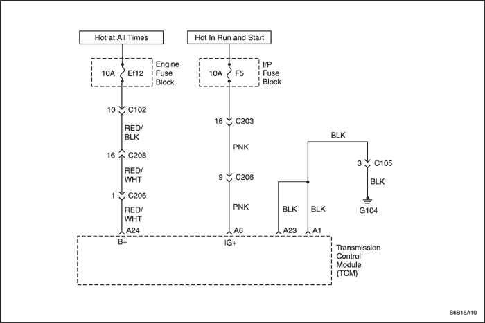
| 6 | Inspect the Ef12,F5 fuse for an open. Was a problem found? | - | Go to Step 7 | Go to Step 8 |
| 7 | Inspect the Ef12,F5 fuse for short. Replace the fuse if necessary. Is the replacement complete? | - | System OK | - |
| 8 | - Turn the ignition ON.
- Measure the voltage of Ef12,F5.
Is the voltage within the values shown? | 9-16v | Go to Step 10 | Go to Step 9 |
| 9 | Repair the fuse voltage supply lines for open. Is the action completed? | - | System OK | - |
| 10 | - Turn the ignition LOCK.
- Disconnect the TCM wiring connector.
- Measure the resistance between Ef12 fuse and terminal A24 of the TCM wiring connector.
Is the resistance within the values shown? | 0Ω | Go to Step 12 | Go to Step 11 |
| 11 | Repair the circuit (between Ef12 and terminal A24) for short to ground and open. Is the repair completed? | - | System OK | - |
| 12 | - Disconnect the C102 connector and TCM connector.
- Turn the ignition ON.
- Measure the voltage of the terminal A24.
Is the voltage within the values shown? | 9-16v | Go to Step 13 | Go to Step 14 |
| 13 | Repair the circuit from Ef12 to terminal A24 of the TCM for short to battery. Is the repair completed? | - | System OK | - |
| 14 | - Turn the ignition LOCK.
- Disconnect the C203 connector.
- Measure the resistance between F5 fuse and terminal A6 of the TCM wiring connector.
Is the resistance within the values shown? | 0Ω | Go to Step 17 | Go to Step 15 |
| 15 | Repair the circuit (between F5 and terminal A6) for short to ground and open. Is the repair completed? | - | System OK | - |
| 16 | - Turn the ignition ON.
- Measure the voltage of the terminal A6.
Is the voltage within the values shown? | 9-16v | Go to Step 17 | Go to Step 18 |
| 17 | Repair the circuit (between F5 and terminal A6) for short to battery. Is the repair completed? | - | System OK | - |
| 18 | - Inspect the transaxle wiring for poor electrical connectors at the transaxle connector.
- Look for possible bent, backed out, deformed, or damaged terminals.
- Check for week terminal tension.
Was a condition found? | - | Verify repair and Go to Step 20 | - |
| 19 | Replace the TCM. Is the replacement complete? | - | Go to Step 20 | - |
| 20 | - After the repair, use a scan tool "clear info" function and road test the vehicle.
- Review the "DTC info".
Has the last test failed or is the current DTC displayed? | - | Begin diagnosis again | Repair verified Exit DTC chart |
Diagnostic Trouble Code (DTC) P0563
System Voltage high
Conditions for Running the DTC
- Ignition ON.
- No failure condition of CAN Bus OFF.
- No failure condition of engine revolution.
- Engine revolution is greater than 400 rpm.
- No failure condition of input speed sensor revolution.
- Input speed sensor revolution is greater than 400 rpm.
- Ignition voltage is less than 20 volts for 1 seconds continuously.
Conditions for Setting the DTC
- Above condition continuously occurs 20 times.
Action Taken When the DTC Sets
- TCM will request the illumination of MIL and store DTC when TCM detects failures on two consecutive ignition cycle.
Conditions for Clearing the DTC
- The TCM turns off the MIL when no further failures detected for three consecutive ignition cycles.
- The scan tool can clear the DTC from the TCM history.
- The TCM clears the DTC from the TCM history memory after forty consecutive warm up cycles without fault.
Cause of Failure
- TCM wiring harness and connectors
- Battery
- TCM
DTC P0563 - System Voltage High
| Step | Action | Value(s) | Yes | No |
| 1 | - Turn the ignition OFF.
- Install the Scan tool.
- Turn the ignition ON, with the engine OFF.
- Run the engine to 600 rpm or greater.
- Record then clear DTC(s).
- Select system voltage on the scan tool.
- Drive the vehicle and observe the scan tool for either of the flowing conditions:
Is the voltage within the values shown? | 9-16v | Go to Step 4 | Go to Step 2 |
| 2 | - Disconnect the battery cable.
- Measure the battery voltage.
Is the voltage within the values shown? | 9-16v | Go to Step 4 | Go to Step 3 |
| 3 | - Replace the battery.
Is the replacement completed? | - | System OK | - |
| 4 | - Turn the headlamp ON.
- Turn the air conditioner ON.
- Run the engine to 600 rpm or greater.
- Observe the scan tool for system voltage.
Is the voltage within the values shown? | 9-16v | Go to Step 6 | Go to Step 5 |
| 5 | - Turn the ignition LOCK.
- Repair the alternator circuit if necessary.
Is the action completed? | - | System OK | - |
| 6 | Inspect the Ef12,F5 fuse for an open. Was a problem found? | - | Go to Step 7 | Go to Step 8 |
| 7 | Inspect the Ef12,F5 fuse for short. Replace the fuse if necessary. Is the replacement complete? | - | System OK | - |
| 8 | - Turn the ignition ON.
- Measure the voltage of Ef12,F5.
Is the voltage within the values shown? | 9-16v | Go to Step 10 | Go to Step 9 |
| 9 | Repair the fuse voltage supply lines for open. Is the action completed? | - | System OK | - |
| 10 | - Turn the ignition LOCK.
- Disconnect the TCM wiring connector.
- Measure the resistance between Ef12 fuse and terminal A24 of the TCM wiring connector.
Is the resistance within the values shown? | 0Ω | Go to Step 12 | Go to Step 11 |
| 11 | Repair the circuit (between Ef12 and terminal A24) for short to ground and open. Is the repair completed? | - | System OK | - |
| 12 | - Disconnect the C102 connector and TCM connector.
- Turn the ignition ON.
- Measure the voltage of the terminal A24.
Is the voltage within the values shown? | 9-16v | Go to Step 13 | Go to Step 14 |
| 13 | Repair the circuit from Ef12 to terminal A24 of the TCM for short to battery. Is the repair completed? | - | System OK | - |
| 14 | - Turn the ignition LOCK.
- Disconnect the C203 connector.
- Measure the resistance between F5 fuse and terminal A6 of the TCM wiring connector.
Is the resistance within the values shown? | 0Ω | Go to Step 17 | Go to Step 15 |
| 15 | Repair the circuit (between F5 and terminal A6) for short to ground and open. Is the repair completed? | - | System OK | - |
| 16 | - Turn the ignition ON.
- Measure the voltage of the terminal A6.
Is the voltage within the values shown? | 9-16v | Go to Step 17 | Go to Step 18 |
| 17 | Repair the circuit (between F5 and terminal A6) for short to battery. Is the repair completed? | - | System OK | - |
| 18 | - Inspect the transaxle wiring for poor electrical connectors at the transaxle connector.
- Look for possible bent, backed out, deformed, or damaged terminals.
- Check for week terminal tension.
Was a condition found? | - | Verify repair and Go to Step 20 | - |
| 19 | Replace the TCM. Is the replacement completed? | - | Go to Step 20 | - |
| 20 | - After the repair, use a scan tool "clear info" function and road test the vehicle.
- Review the "DTC info".
Has the last test failed or is the current DTC displayed? | - | Begin diagnosis again | Repair verified Exit DTC chart |
Diagnostic Trouble Code (DTC) P0601
Internal Control Module Memory Checksum Error
Conditions for Running the DTC
- TCM detects that the value of check sum calculations excuted after ignition ON.
- If there are a difference from the correct check sum value stored in flash ROM, the second calculation is made differences twice detection is criteria.
Conditions for Setting the DTC
- Above detection continuously occurs 1 times.
Action Taken When the DTC Sets
- TCM will request the illumination of MIL and store DTC when TCM detects a failure on the first consecutive ignition cycle.
Conditions for Clearing the DTC
- The TCM turns off the MIL when no further failures detected for three consecutive ignition cycles.
- The scan tool can clear the DTC from the TCM history.
- The TCM clears the DTC from the TCM history memory after forty consecutive warm up cycles without fault.
Cause of Failure
- Harness or connector between TCM and ECM
- ECM
- TCM
DTC P0601 - Internal Control Module Memory Checksum Error
| Step | Action | Value(s) | Yes | No |
| 1 | - Turn the ignition OFF.
- Install the Scan tool.
- With the engine OFF, turn the ignition switch to the ON position.
- Select Store Freeze Frame/Failure Records from the Diagnostic Trouble Codes Information menu.
- Store Freeze Frame/Failure Records.
- Select Clear DTC Information from the Diagnostic Trouble Codes Information menu.
- Clear DTC Information.
- Perform one vehicle drive cycle.
Is the Malfunction Indicator Lamp (MIL) ON? | - | Go to Step 2 | Inspect Transmission Control Module (TCM) wiring harness and connector for signs of an intermittent condition. Repair as necessary. |
| 2 | - Select Request DTC by Status from the Diagnostic Trouble Codes Information menu.
- Request DTC by Status.
Is DTC P0601 displayed? | - | Replace the Transmission Control Module (TCM) | Inspect Transmission Control Module (TCM) wiring harness and connector for signs of an intermittent condition. Repair as necessary. |
Diagnostic Trouble Code (DTC) P0604
Internal Control Module Random Access Memory (RAM) Error
Conditions for Running the DTC
- The Transmission Control Module (TCM) cannot carry out the four RAM initialization routines.
- TCM detects that the RAM cannot be written and read correctly.
Conditions for Setting the DTC
- Above detection continuously occurs 1 time.
Action Taken When the DTC Sets
- TCM will request the illumination of MIL and store DTC when TCM detects failures on two consecutive ignition cycle.
Conditions for Clearing the DTC
- The TCM turns off the MIL when no further failures detected for three consecutive ignition cycles.
- The scan tool can clear the DTC from the TCM history.
- The TCM clears the DTC from the TCM history memory after forty consecutive warm up cycles without fault.
Cause of Failure
- Harness or connector between TCM and ECM
- ECM
- TCM
DTC P0604 - Internal Control Module Random Access Memory (RAM) Error
| Step | Action | Value(s) | Yes | No |
| 1 | - Turn the ignition OFF.
- Install the Scan tool.
- With the engine OFF, turn the ignition switch to the ON position.
- Select Store Freeze Frame/Failure Records from the Diagnostic Trouble Codes Information menu.
- Store Freeze Frame/Failure Records.
- Select Clear DTC Information from the Diagnostic Trouble Codes Information menu.
- Clear DTC Information.
- Perform two vehicle drive cycles.
Is the Malfunction Indicator Lamp (MIL) ON? | - | Go to Step 2 | Inspect Transmission Control Module (TCM) wiring harness and connector for signs of an intermittent condition. Repair as necessary. |
| 2 | - Select Request DTC by Status from the Diagnostic Trouble Codes Information menu.
- Request DTC by Status.
Is DTC P0604 displayed? | - | Replace the Transmission Control module (TCM) | Inspect Transmission Control Module (TCM) wiring harness and connector for signs of an intermittent condition. Repair as necessary. |
Diagnostic Trouble Code (DTC) P0705
Transmission Range (TR) Switch Circuit Malfunction (No Signal)
Conditions for Running the DTC
- No failure condition of engine revolution.
- No failure condition of CAN Bus OFF.
- No emergency mode.
- TCM detects no signal of TR switch circuit for 2 seconds continuously.
Conditions for Setting the DTC
- TCM detects no signal of TR switch circuit for 28 seconds continuously from short of detection.
- No signal of TR switch circuit.
- Vehicle speed is 30 km/h (19 mph) or greater.
Action Taken When the DTC Sets
- TCM will request the illumination of MIL and store DTC when TCM detects failures on two consecutive ignition cycle.
- TCM judges the D range.
- No timing solenoid control for N-D
- No self-learning control
- No lockup
- No prevent reverse gear control
Conditions for Clearing the DTC
- The TCM turns off the MIL when no further failures detected for three consecutive ignition cycles.
- The scan tool can clear the DTC from the TCM history.
- The TCM clears the DTC from the TCM history memory after forty consecutive warm up cycles without fault.
- TCM detects single "D range" signal of the TR switch.
Cause of Failure
- Wiring harness or connector between TR switch and TCM
- TR switch
- TCM
DTC P0705 - Transmission Range (TR) Switch Circuit Malfunction (No Signal)
| Step | Action | Value(s) | Yes | No |
| 1 | - Turn the ignition OFF.
- Install the Scan tool.
- With the engine OFF, turn the ignition switch to the ON position.
- Select Store Freeze Frame/Failure Records from the Diagnostic Trouble Codes Information menu.
- Store Freeze Frame/Failure Records.
- Select Clear DTC Information from the Diagnostic Trouble Codes Information menu.
- Clear DTC Information.
- Perform two vehicle drive cycles.
Is the Malfunction Indicator Lamp (MIL) ON? | - | Go to Step 2 | Repair the temporary connection failure of connector (Refer to "Wiring Harness and Connector Inspection" in this section.) |
| 2 | - Select Request DTC by Status from the Diagnostic Trouble Codes Information menu.
- Request DTC by Status.
Is DTC P0705 displayed? | - | Go to Step 3 | Repair the temporary connection failure of connector (Refer to "Wiring Harness and Connector Inspection" in this section.) |
| 3 | - Turn the ignition OFF.
- Inspect the continuity between the vehicle harness and the Transmission Range (TR) Switch.
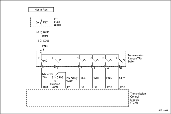
- Disconnect the TCM connector (X-1) of the vehicle harness and inspect the continuity for the each terminal according to the position of the select lever.
- P : B20
- R : B1
- N : B8
- D : B7
- 2 : B19
- 1 : B18
Does the inspection OK? | - | Go to Step 4 | Go to Step 5 |
| 4 | - Estimate the failure of between the vehicle wiring harness connector and TCM.
- Inspect the connector. Refer to "Wiring Harness and Connector Inspection" in this section.
- Inspect the connection condition between the TCM connectors (C-1).
Is the connection condition OK? | - | Go to Step 6 | Repair the wiring harness connectors. |
| 5 | - Estimate the failure of between the vehicle harness and TR switch.
- Disconnect the connector (X-2) of the vehicle harness and inspect the continuity between the terminals. Refer to "Wiring Harness and Connector Inspection" in this section.
Is the condition of TR switch OK? | - | Go to Step 7 | Replace the TR switch. |
| 6 | - Replace the master TCM.
- Perform the reproducing test under user condition after confirming no DTC.
Is DTC displayed? | - | Repair the temporary connection failure of connector (Refer to "Wiring Harness and Connector Inspection" in this section). | Replace the TCM. |
| 7 | - Estimate the failure of the vehicle harness.
- Inspect continuity and short circuit for the vehicle harness and inspect the connection condition between connectors (C-2). Refer to "Wiring Harness and Connector Inspection" in this section.
Is the condition OK? | - | Repair the temporary connection failure of connector | Replace the vehicle harness or adjustment between connectors. |
Diagnostic Trouble Code (DTC) P0706
Transmission Range (TR) Switch Circuit Malfunction (Short)
Conditions for Running the DTC
- No failure condition of engine revolution.
- No failure condition of CAN Bus OFF.
- No emergency mode.
- TCM detects 2 or more signals of TR switch circuit for 2 seconds continuously.
Conditions for Setting the DTC
- Above detection continuously occurs 5 times.
Action Taken When the DTC Sets
- TCM will request the illumination of MIL and store DTC when TCM detects failures on two consecutive ignition cycle.
- TCM judges with the priority. (D>2>L>R>N>P)
- No timing solenoid control for N-D
- No self-learning control
- No lockup
- No prevent reverse gear control
Conditions for Clearing the DTC
- The TCM turns off the MIL when no further failures detected for three consecutive ignition cycles.
- The scan tool can clear the DTC from the TCM history.
- The TCM clears the DTC from the TCM history memory after forty consecutive warm up cycles without fault.
- TCM detects single "D range" signal of the TR switch.
Cause of Failure
- Wiring harness or connector between TR switch and TCM
- TR switch
- TCM
DTC P0706 - Transmission Range (TR) Switch Circuit Malfunction (Short)
| Step | Action | Value(s) | Yes | No |
| 1 | - Turn the ignition OFF.
- Install the Scan tool.
- With the engine OFF, turn the ignition switch to the ON position.
- Select Store Freeze Frame/Failure Records from the Diagnostic Trouble Codes Information menu.
- Store Freeze Frame/Failure Records.
- Select Clear DTC Information from the Diagnostic Trouble Codes Information menu.
- Clear DTC Information.
- Perform two vehicle drive cycles.
Is the Malfunction Indicator Lamp (MIL) ON? | - | Go to Step 2 | Repair the temporary connection failure of connector (Refer to "Wiring Harness and Connector Inspection" in this section.) |
| 2 | - Select Request DTC by Status from the Diagnostic Trouble Codes Information menu.
- Request DTC by Status.
Is DTC P0706 displayed? | - | Go to Step 3 | Repair the temporary connection failure of connector (Refer to "Wiring Harness and Connector Inspection" in this section.) |
| 3 | - Turn the ignition OFF.
- Inspect the continuity between the vehicle harness and the Transmission Range (TR) Switch.
- Disconnect the TCM connector (X-1) of the vehicle harness and inspect the continuity for the each terminal according to the position of the select lever.
- P : B20
- R : B1
- N : B8
- D : B7
- 2 : B19
- 1 : B18
Does the inspection OK? | - | Go to Step 4 | Go to Step 5 |
| 4 | - Estimate the failure of between the vehicle wiring harness connector and TCM.
- Inspect the connector. Refer to "Wiring Harness and Connector Inspection" in this section.
- Inspect the connection condition between the TCM connectors (C-1).
Is the connection condition OK? | - | Go to Step 6 | Repair the wiring harness connectors. |
| 5 | - Estimate the failure of between the vehicle harness and TR switch.
- Disconnect the connector (X-2) of the vehicle harness and inspect the continuity between the terminals. Refer to "Wiring Harness and Connector Inspection" in this section.
Is the condition of TR switch OK? | - | Go to Step 7 | Replace the TR switch. |
| 6 | - Replace the master TCM.
- Perform the reproducing test under user condition after confirming no DTC.
Is DTC displayed? | - | Repair the temporary connection failure of connector (Refer to "Wiring Harness and Connector Inspection" in this section). | Replace the TCM. |
| 7 | - Estimate the failure of the vehicle harness.
- Inspect continuity and short circuit for the vehicle harness and inspect the connection condition between connectors (C-2). Refer to "Wiring Harness and Connector Inspection" in this section.
Is the condition OK? | - | Repair the temporary connection failure of connector | Replace the vehicle harness or adjustment between connectors. |
Diagnostic Trouble Code (DTC) P0711
Transmission Fluid Temperature (TFT) Sensor Circuit Performance
Conditions for Running the DTC
- Oil temperature is less than 15°C (59°F).
- D, 2 or L range.
- Vehicle speed is 40km/h (25mph) or greater at 1 time.
- Above coditions continues for 10 minutes.
Conditions for Setting the DTC
- Above detection continuously occurs 1 time.
Action Taken When the DTC Sets
- TCM will request the illumination of MIL and store DTC when TCM detects a failure on the first ignition cycle.
- No timing solenoid control for N-D
Conditions for Clearing the DTC
- The TCM turns off the MIL when no further failures detected for three consecutive ignition cycles.
- The scan tool can clear the DTC from the TCM history.
- The TCM clears the DTC from the TCM history memory after forty consecutive warm up cycles without fault.
- TCM detects the temperature of the transmission fluid is between 0°C (32°F) and 150°C (302°F) for 10 seconds continuously.
Cause of Failure
- Wiring harness or connector between Transmission Fluid Temperature (TFT) sensor and TCM
- TFT sensor
- TCM
DTC P0711 - Transmission Fluid Temperature (TFT) Sensor Circuit Performance
| Step | Action | Value(s) | Yes | No |
| 1 | - Turn the ignition OFF.
- Install the Scan tool.
- With the engine OFF, turn the ignition switch to the ON position.
- Select Store Freeze Frame/Failure Records from the Diagnostic Trouble Codes Information menu.
- Store Freeze Frame/Failure Records.
- Select Clear DTC Information from the Diagnostic Trouble Codes Information menu.
- Clear DTC Information.
- Perform one vehicle drive cycle.
Is the Malfunction Indicator Lamp (MIL) ON? | - | Go to Step 2 | Repair the temporary connection failure of connector (Refer to "Wiring Harness and Connector Inspection" in this section.) |
| 2 | - Select Request DTC by Status from the Diagnostic Trouble Codes Information menu.
- Request DTC by Status.
Is DTC P0711 displayed? | - | Go to Step 3 | Repair the temporary connection failure of connector (Refer to "Wiring Harness and Connector Inspection" in this section.) |
| 3 | - Turn the ignition OFF.
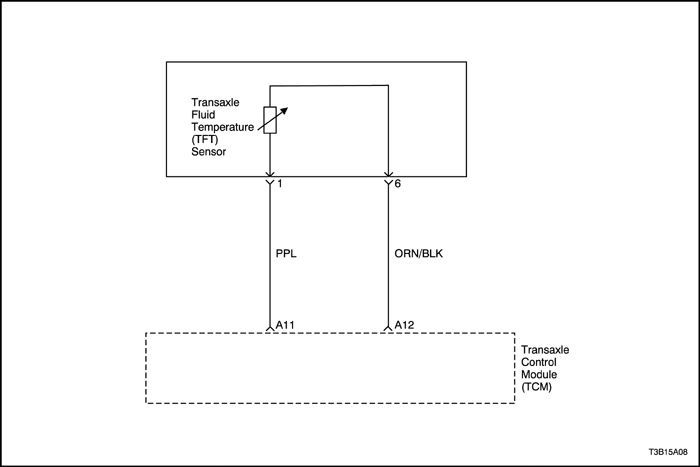
- Inspect the resistance between the vehicle harness and Transmission Fluid Temperature (TFT) sensor. Refer to "Unit Inspection" in this section.
- Disconnect the TCM connector (X-1) and inspect the resistance between the terminal A11 and A12.
Is the measurement within the specified value? | 10°C (50°F): 5.80-7.09 kΩ 110°C (230°F): 0.231-0.263 kΩ | Go to Step 4 | Go to Step 5 |
| 4 | - Estimate the failure of between the vehicle wiring harness connector and TCM.
- Inspect the connector. Refer to "Wiring Harness and Connector Inspection" in this section.
- Inspect the connection condition between the connectors (C-1).
Is the connection condition OK? | - | Go to Step 6 | Repair the wiring harness connectors. |
| 5 | - Estimate the failure of between the vehicle harness and TFT sensor.
- Disconnect the connector (X-3) of T/M wire and inspect the resistance between TFT sensor connector terminal 1 and 6.
Is the measurement within the specified value? | 10°C (50°F): 5.80-7.09 kΩ 110°C (230°F): 0.231-0.263 kΩ | Go to Step 7 | Go to Step 8 |
| 6 | - Replace the master TCM.
- Perform the reproducing test under user condition after confirming no DTC.
Is DTC displayed? | - | Repair the temporary connection failure of connector (Refer to "Wiring Harness and Connector Inspection" in this section). | Replace the TCM. |
| 7 | - Estimate the failure of the vehicle wiring harness or between connectors.
- Inspect continuity and short circuit for the vehicle wiring harness and inspect the connection condition between connectors (C-3). Refer to "Wiring Harness and Connector Inspection" in this section.
Is the condition OK? | - | Repair the temporary connection failure of connector | Replace the vehicle harness or adjustment between connectors |
| 8 | - Estimate the failure of T/M wire or between connectors of TFT sensor.
- Inspect fluid temperature. Refer to "Unit Inspection" in this section.
Is the problem found? | - | Replace TFT sensor | Go to Step 9 |
| 9 | - Estimate the failure of T/M wire.
- Inspect continuity and short circuit for the T/M wire and inspect the connection condition between connectors (C-3). Refer to "Wiring Harness and Connector Inspection" in this section.
Is the condition OK? | - | Repair the temporary connection failure of connector | Replace the T/M wire or adjustment between connectors |
Diagnostic Trouble Code (DTC) P0712
Transmission Fluid Temperature (TFT) Sensor Circuit Low Input
Conditions for Running the DTC
- No emergency mode.
- No failure condition of CAN Bus OFF.
- Input A/D value is less than 10 (0.05 volt) for 10 seconds continuously.
Conditions for Setting the DTC
- Above detection continuously occurs 30 times.
Action Taken When the DTC Sets
- TCM will request the illumination of MIL and store DTC when TCM detects a failure on the first ignition cycle.
- TCM judges the temperature of the transmission fluid is 200°C (392°F).
- No lockup control
- No 4th gear
- No self-learning control
- No timing solenoid control for N-D
Conditions for Clearing the DTC
- The TCM turns off the MIL when no further failures detected for three consecutive ignition cycles.
- The scan tool can clear the DTC from the TCM history.
- The TCM clears the DTC from the TCM history memory after forty consecutive warm up cycles without fault.
- TCM detects the temperature of the transmission fluid is between 0°C (32°) and 150°C (302°F) for 10 seconds continuously.
Cause of Failure
- Wiring harness or connector between Transmission Fluid Temperature (TFT) sensor and TCM
- TFT sensor
- TCM
DTC P0712 - Transmission Fluid Temperature (TFT) Sensor Circuit Low Input
| Step | Action | Value(s) | Yes | No |
| 1 | - Turn the ignition OFF.
- Install the Scan tool.
- With the engine OFF, turn the ignition switch to the ON position.
- Select Store Freeze Frame/Failure Records from the Diagnostic Trouble Codes Information menu.
- Store Freeze Frame/Failure Records.
- Select Clear DTC Information from the Diagnostic Trouble Codes Information menu.
- Clear DTC Information.
- Perform one vehicle drive cycle.
Is the Malfunction Indicator Lamp (MIL) ON? | - | Go to Step 2 | Repair the temporary connection failure of connector (Refer to "Wiring Harness and Connector Inspection" in this section.) |
| 2 | - Select Request DTC by Status from the Diagnostic Trouble Codes Information menu.
- Request DTC by Status.
Is DTC P0712 displayed? | - | Go to Step 3 | Repair the temporary connection failure of connector (Refer to "Wiring Harness and Connector Inspection" in this section.) |
| 3 | - Turn the ignition OFF.
- Inspect the resistance between the vehicle harness and Transmission Fluid Temperature (TFT) sensor. Refer to "Unit Inspection" in this section.
- Disconnect the TCM connector (X-1) and inspect the resistance between the terminal A11 and A12.
Is the measurement within the specified value? | 10°C (50°F): 5.80-7.09 kΩ 110°C (230°F): 0.231-0.263 kΩ | Go to Step 4 | Go to Step 5 |
| 4 | - Estimate the failure of between the vehicle wiring harness connector and TCM.
- Inspect the connector. Refer to "Wiring Harness and Connector Inspection" in this section.
- Inspect the connection condition between the connectors (C-1).
Is the connection condition OK? | - | Go to Step 6 | Repair the wiring harness connectors. |
| 5 | - Estimate the failure of between the vehicle harness and TFT sensor.
- Disconnect the connector (X-3) of T/M wire and inspect the resistance between TFT sensor connector terminal 1 and 6.
Is the measurement within the specified value? | 10°C (50°F): 5.80-7.09 kΩ 110°C (230°F): 0.231-0.263 kΩ | Go to Step 7 | Go to Step 8 |
| 6 | - Replace the master TCM.
- Perform the reproducing test under user condition after confirming no DTC.
Is DTC displayed? | - | Repair the temporary connection failure of connector (Refer to "Wiring Harness and Connector Inspection" in this section). | Replace the TCM. |
| 7 | - Estimate the failure of the vehicle wiring harness or between connectors.
- Inspect continuity and short circuit for the vehicle wiring harness and inspect the connection condition between connectors (C-3). Refer to "Wiring Harness and Connector Inspection" in this section.
Is the condition OK? | - | Repair the temporary connection failure of connector | Replace the vehicle harness or adjustment between connectors |
| 8 | - Estimate the failure of T/M wire or between connectors of TFT sensor.
- Inspect fluid temperature. Refer to "Unit Inspection" in this section.
Is the problem found? | - | Replace TFT sensor | Go to Step 9 |
| 9 | - Estimate the failure of T/M wire.
- Inspect continuity and short circuit for the T/M wire and inspect the connection condition between connectors (C-3). Refer to "Wiring Harness and Connector Inspection" in this section.
Is the condition OK? | - | Repair the temporary connection failure of connector | Replace the T/M wire or adjustment between connectors |
Diagnostic Trouble Code (DTC) P0713
Transmission Fluid Temperature (TFT) Sensor Circuit High Input
Conditions for Running the DTC
- Engine coolant temperature is greater than 50°C (122°F).
- No failure condition of engine coolant temperature.
- Input A/D value is greater than 1000 (4.89 volts) for 1 second continuously.
Conditions for Setting the DTC
- Above detection continuously occurs 12 times.
Action Taken When the DTC Sets
- TCM will request the illumination of MIL and store DTC when TCM detects a failure on the first ignition cycle.
- TCM judges the temperature of the transmission fluid is 200°C (392°F).
- No lockup control
- No 4th gear
- No self-learning control
- No timing solenoid control for N-D
Conditions for Clearing the DTC
- The TCM turns off the MIL when no further failures detected for three consecutive ignition cycles.
- The scan tool can clear the DTC from the TCM history.
- The TCM clears the DTC from the TCM history memory after forty consecutive warm up cycles without fault.
- TCM detects the temperature of the transmission fluid is between 0°C (32°F) and 150°C (302°F) for 10 seconds continuously.
Cause of Failure
- Wiring harness or connector between Transmission Fluid Temperature (TFT) sensor and TCM
- TFT sensor
- TCM
DTC P0713 - Transmission Fluid Temperature (TFT) Sensor Circuit High Input
| Step | Action | Value(s) | Yes | No |
| 1 | - Turn the ignition OFF.
- Install the Scan tool.
- With the engine OFF, turn the ignition switch to the ON position.
- Select Store Freeze Frame/Failure Records from the Diagnostic Trouble Codes Information menu.
- Store Freeze Frame/Failure Records.
- Select Clear DTC Information from the Diagnostic Trouble Codes Information menu.
- Clear DTC Information.
- Perform one vehicle drive cycle.
Is the Malfunction Indicator Lamp (MIL) ON? | - | Go to Step 2 | Repair the temporary connection failure of connector (Refer to "Wiring Harness and Connector Inspection" in this section.) |
| 2 | - Select Request DTC by Status from the Diagnostic Trouble Codes Information menu.
- Request DTC by Status.
Is DTC P0713 displayed? | - | Go to Step 3 | Repair the temporary connection failure of connector (Refer to "Wiring Harness and Connector Inspection" in this section.) |
| 3 | - Turn the ignition OFF.
- Inspect the resistance between the vehicle harness and Transmission Fluid Temperature (TFT) sensor. Refer to "Unit Inspection" in this section.
- Disconnect the TCM connector (X-1) and inspect the resistance between the terminal A11 and A12.
Is the measurement within the specified value? | 10°C (50°F): 5.80-7.09 kΩ 110°C (230°F): 0.231-0.263 kΩ | Go to Step 4 | Go to Step 5 |
| 4 | - Estimate the failure of between the vehicle wiring harness connector and TCM.
- Inspect the connector. Refer to "Wiring Harness and Connector Inspection" in this section.
- Inspect the connection condition between the connectors (C-1).
Is the connection condition OK? | - | Go to Step 6 | Repair the wiring harness connectors. |
| 5 | - Estimate the failure of between the vehicle harness and TFT sensor.
- Disconnect the connector (X-3) of T/M wire and inspect the resistance between TFT sensor connector terminal 1 and 6.
Is the measurement within the specified value? | 10°C (50°F): 5.80-7.09 kΩ 110°C (230°F): 0.231-0.263 kΩ | Go to Step 7 | Go to Step 8 |
| 6 | - Replace the master TCM.
- Perform the reproducing test under user condition after confirming no DTC.
Is DTC displayed? | - | Repair the temporary connection failure of connector (Refer to "Wiring Harness and Connector Inspection" in this section). | Replace the TCM. |
| 7 | - Estimate the failure of the vehicle wiring harness or between connectors.
- Inspect continuity and short circuit for the vehicle wiring harness and inspect the connection condition between connectors (C-3). Refer to "Wiring Harness and Connector Inspection" in this section.
Is the condition OK? | - | Repair the temporary connection failure of connector | Replace the vehicle harness or adjustment between connectors |
| 8 | - Estimate the failure of T/M wire or between connectors of TFT sensor.
- Inspect fluid temperature. Refer to "Unit Inspection" in this section.
Is the problem found? | - | Replace TFT sensor | Go to Step 9 |
| 9 | - Estimate the failure of T/M wire.
- Inspect continuity and short circuit for the T/M wire and inspect the connection condition between connectors (C-3). Refer to "Wiring Harness and Connector Inspection" in this section.
Is the condition OK? | - | Repair the temporary connection failure of connector | Replace the T/M wire or adjustment between connectors |
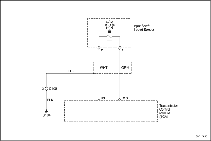
Diagnostic Trouble Code (DTC) P0717
Input Shaft Speed (ISS) Sensor Circuit No Signal
Conditions for Running the DTC
- No emergency mode.
- No failure condition of engine revolution.
- No failure condition of CAN Bus OFF.
- No failure condition of output speed sensor and TR switch .
- Output speed sensor revolution is greater than 600 rpm.
- TCM detects no pulse of input speed sensor while TCM detects 4 pulses of the output speed sensor.
Conditions for Setting the DTC
- Above detection continuously occurs 500 times.
Action Taken When the DTC Sets
- TCM will request the illumination of MIL and store DTC when TCM detects a failure on the first ignition cycle.
- No lockup control
- No engine torque reduction control
- No engagement pressure control
- No 4th gear
- No self-learning control
- No timing solenoid control for N-D
Conditions for Clearing the DTC
- The TCM turns off the MIL when no further failures detected for three consecutive ignition cycles.
- The scan tool can clear the DTC from the TCM history.
- The TCM clears the DTC from the TCM history memory after forty consecutive warm up cycles without fault.
- TCM detects 250 pulses of ISS while failure detection is not achieved.
Cause of Failure
- Wiring harness or connector between Input Shaft Speed (ISS) sensor and TCM
- ISS sensor
- TCM
DTC P0717 - Input Shaft Speed (ISS) Sensor Circuit No Signal
| Step | Action | Value(s) | Yes | No |
| 1 | - Turn the ignition OFF.
- Install the Scan tool.
- With the engine OFF, turn the ignition switch to the ON position.
- Select Store Freeze Frame/Failure Records from the Diagnostic Trouble Codes Information menu.
- Store Freeze Frame/Failure Records.
- Select Clear DTC Information from the Diagnostic Trouble Codes Information menu.
- Clear DTC Information.
- Perform one vehicle drive cycle.
Is the Malfunction Indicator Lamp (MIL) ON? | - | Go to Step 2 | Repair the temporary connection failure of connector (Refer to "Wiring Harness and Connector" in this section.) |
| 2 | - Select Request DTC by Status from the Diagnostic Trouble Codes Information menu.
- Request DTC by Status.
Is DTC P0717 displayed? | - | Go to Step 3 | Repair the temporary connection failure of connector (Refer to "Wiring Harness and Connector" in this section.) |
| 3 | - Turn the ignition OFF.
- Inspect the resistance between the vehicle harness and Input Shaft Speed (ISS) sensor. Refer to "Unit Inspection" in this section.
- Disconnect the TCM connector (X-1) and inspect the resistance between the terminal B6 and B16.
Is the measurement within the specified value? | 20°C (68°F): 560-680 Ω | Go to Step 4 | Go to Step 5 |
| 4 | - Estimate the failure of between the vehicle wiring harness connector and TCM.
- Inspect the connector. Refer to "Wiring Harness and Connector Inspection" in this section.
- Inspect the connection condition between the connectors (C-1).
Is the connection condition OK? | - | Go to Step 6 | Repair the wiring harness connectors. |
| 5 | - Estimate the failure of T/M wire or between the connectors of ISS sensor.
- Disconnect the ISS sensor connector (X-5) and inspect the resistance between terminals 1 and 2.
Is the measurement within the specified value? | 20°C (68°F): 560-680Ω | Go to Step 7 | Replace the ISS sensor |
| 6 | - Replace the master TCM.
- Perform the reproducing test under user condition after confirming no DTC.
Is DTC displayed? | - | Repair the temporary connection failure of connector (Refer to "Wiring Harness and Connector" in this section.) | Replace the TCM. |
| 7 | - Estimate the failure of T/M wire.
- Inspect continuity and short circuit for the T/M wire and inspect the connection condition between connectors (C-5). Refer to "Wiring Harness and Connector" in this section
Is the condition OK? | - | Repair the temporary connection failure of connector | Replace the T/M wire or adjustment between connectors |
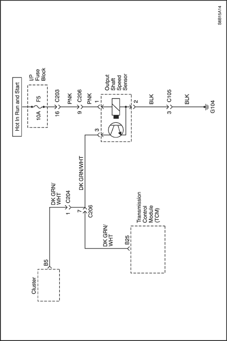
Diagnostic Trouble Code (DTC) P0722
Output Shaft Speed (OSS) Sensor Circuit No Signal
Conditions for Running the DTC
- No emergency mode.
- No failure condition of engine revolution.
- No failure condition of CAN Bus OFF.
- No failure condition of input speed sensor and TR switch .
- Output speed sensor revolution is greater than 300 rpm.
- TCM detects no pulse of output speed sensor while TCM detects 178 pulses of the input speed sensor.
Conditions for Setting the DTC
- Above detection continuously occurs 500 times.
Action Taken When the DTC Sets
- TCM will request the illumination of MIL and store DTC when TCM detects a failure on the first ignition cycle.
- No lockup control
- No engine torque reduction control
- No engagement pressure control
- No 4th gear
- No self-learning control
- No prevent reverse gear control
- No timing solenoid control for N-D.
Conditions for Clearing the DTC
- The TCM turns off the MIL when no further failures detected for three consecutive ignition cycles.
- The scan tool can clear the DTC from the TCM history.
- The TCM clears the DTC from the TCM history memory after forty consecutive warm up cycles without fault.
- TCM detects 250 pulses of Output Shaft Speed (OSS) sensor while failure detection is not achieved.
Cause of Failure
- Wiring harness or connector between Output Shaft Speed (OSS) sensor and TCM
- OSS sensor
- TCM
DTC - P0722 Output Shaft Speed (OSS) sensor Circuit No Signal
| Step | Action | Value(s) | Yes | No |
| 1 | - Turn the ignition OFF.
- Install the Scan tool.
- With the engine OFF, turn the ignition switch to the ON position.
- Select Store Freeze Frame/Failure Records from the Diagnostic Trouble Codes Information menu.
- Store Freeze Frame/Failure Records.
- Select Clear DTC Information from the Diagnostic Trouble Codes Information menu.
- Clear DTC Information.
- Perform one vehicle drive cycle.
Is the Malfunction Indicator Lamp (MIL) ON? | - | Go to Step 2 | Repair the temporary connection failure of connector (Refer to "Wiring Harness and Connector Inspection" in this section.) |
| 2 | - Select Request DTC by Status from the Diagnostic Trouble Codes Information menu.
- Request DTC by Status.
Is DTC P0722 displayed? | - | Go to Step 3 | Repair the temporary connection failure of connector (Refer to "Wiring Harness and Connector Inspection" in this section.) |
| 3 | - Turn the ignition OFF.
- Inspect the voltage between vehicle harness and the Output Shaft Speed (OSS) sensor.
- Disconnect the connector (X-1) of the vehicle harness.
- Connect the voltmeter to monitor the voltage between terminal B25 and ground.
- Turn ignition ON and lift up the vehicle.
- Check the voltage change from approximately 0 v to 12 v when the wheel is turned slowly.
Does the measurement change within the specified value? | 0-12 v | Go to Step 4 | Go to Step 5 |
| 4 | - Estimate the failure of between the vehicle wiring harness connector and TCM.
- Inspect the connector. Refer to "Wiring Harness and Connector Inspection" in this section.
- Inspect the connection condition between the connectors (C-1).
Is the connection condition OK? | - | Go to Step 6 | Repair the wiring harness connectors. |
| 5 | - Estimate the failure of T/M wire or between the connectors of OSS sensor.
- Inspect the OSS sensor. Refer to "Unit Inspection" in this section
Is the condition of OSS sensor OK? | - | Go to Step 7 | Replace the OSS sensor |
| 6 | - Replace the master TCM.
- Perform the reproducing test under user condition after confirming no DTC.
Is DTC displayed? | - | Repair the temporary connection failure of connector (Refer to "Wiring Harness and Connector Inspection" in this section.) | Replace the TCM. |
| 7 | - Estimate the failure of T/M wire.
- Inspect continuity and short circuit for the T/M wire and inspect the connection condition between connectors (C-4). Refer to "Wiring Harness and Connector Inspection" in this section.
Is the condition OK? | - | Repair the temporary connection failure of connector | Replace the T/M wire or adjustment between connectors |
 | |  | |
| © Copyright Chevrolet Europe. All rights reserved |


