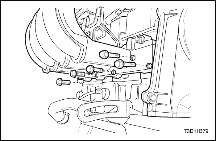
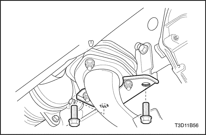
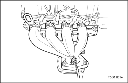
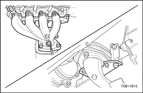
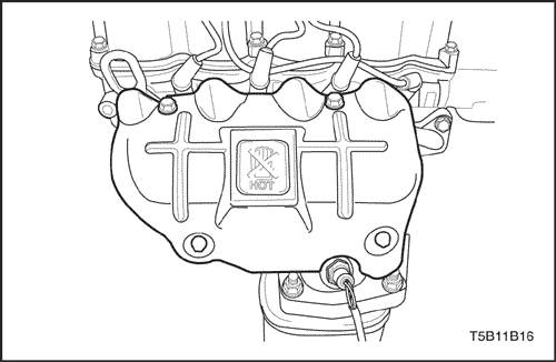
Tighten the exhaust manifold heat
shield bolts to 10 N•m (89
lb-in).
Engine
Removal
Procedure
Important : On vehicle equipped with a
manual transaxle, the manual transaxle must be removed
before engine removal. Refer to Section 5B,
Five-Speed Manual
Transaxle.
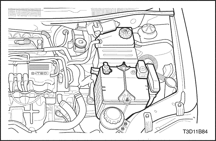
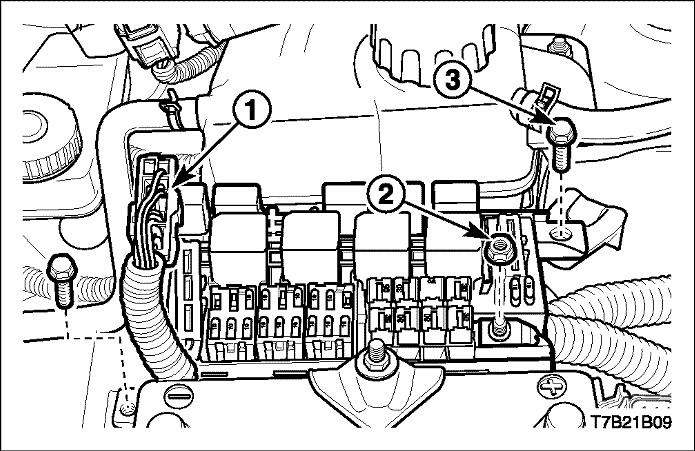
Remove
the fuel pump fuse.
Start the engine. After it stalls,
crank the engine for 10 seconds to rid the fuel system of fuel
pressure.
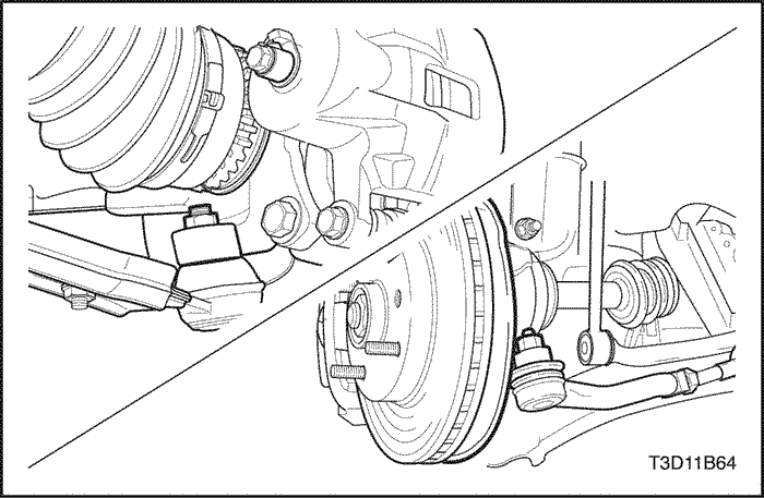
Install the
air conditioning low/high pressure pipe O-ring seal,
select/shift cable pin/washer/E-ring, tie rod end joint
castellated nut cotter pin, stabilizer castellated nut cotter
pin for loss.
Refill the transaxle oil, power steering
oil and coolant after finishing all installation
procedure.
Reset the engine control module
(ECM).
Recharge the air conditioning system and check
the oil/coolant level.
Start the engine and check the
engine for the normal operation.